Ⅰ、Summarize
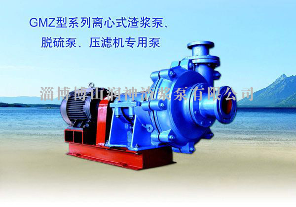
As a single stage single suck and axial sucking cantilever horizontal centrifugal pump, the GMZ series slurry pump can be applied to many industries, such as metallurgy、mine、electric power、desulfurization、aeroconcrete、chemical engineering and so on. This pump can be used for conveying the corrosive slurry with large quantity solid material.
1、The flow components of GMZ slurry pump adopt high strength and wear resistant material, so it applies to deep-etching 、high concentration and large particle slurry, and within the maximum working pressure, this pump can be used in multilevel series .
2、According to different sucking medium, the GMZ slurry pump can be changed with different flow components, generally, there are wear-resistant alloy Cr26、Cr 28、No.2 wear-resistant、A49、CD4. For the feature of high content chlorine liquid ion in flue gas desulfurization flurry, our company introduced wear-resistant and anticorrosion Cr30, which is the most advanced around the world, from France, in Cr30, the Mo、Cr、Cu、N as well as a certain active elements, it has excellent anti scour as well as better strength and toughness.
3、Model and meaning: Take GMZ65-20-40 as example
GMZ―― High efficiency wear-resistance slurry pump
65―― Outlet diameter (mm)
20 ――Pump lift (m)
40――Flow rate (m3/h)
Ⅱ、Structuraldra wing
Cooling water inlet Cooling water outlet
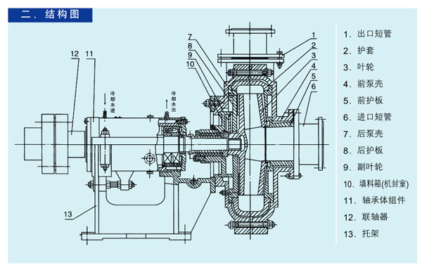
1 Outlet stub tube
2 Protecting jacket
3 Impeller
4 Front pump shell
5 Front fender
6 Inlet stub tube
7 Back pump shell
8 Back fender
9 Auxiliary impeller
10 Stuffing-box(Mechanical sealing chamber)
11 Bearing assembly
12 Coupling
13 Bracket
Structure specification
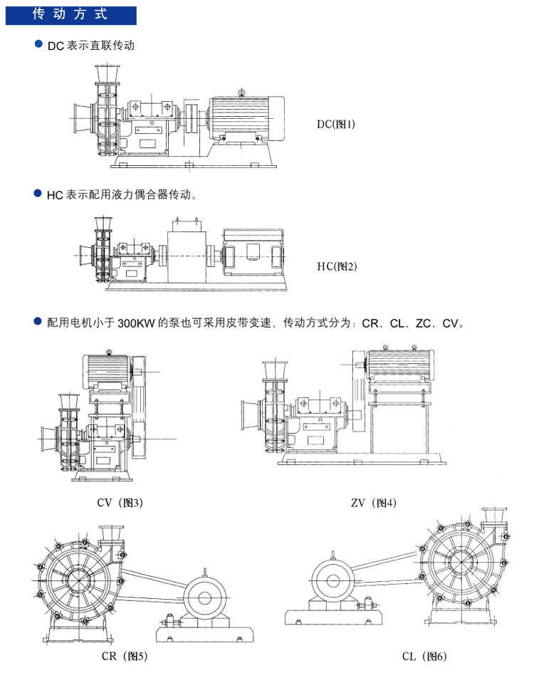
Except pump head(including pump shell、spiral case、front and back fender 、impeller and so on), the rest of GMZ series pump are similar and adopt the same driving mechanism, in the following, given the instruction to pump head、shaft gland part and driving part respectively:
1. Pump head: the GMZ series pump is dual-pump shell structure, that is front and back pump shell as well as changeable flow parts (including impeller、spiral case、front and back fenders), the back and front fender adopt gray pig iron or ductile cast iron for manufacturing, it is open in middle in vertical way and use bolts for connection, there is spigot on the back pump shell and connected with bracket with bolts, additionally, the discharge opening of pump can be installed by eight angles rotation, the back and front cover plates of impeller are equipped with back blade for reducing the leakage, and so the useful life of pump can be improved greatly. Between the impeller and shaft, adopt threaded connection for prevention of reversion. For each kinds of pump, the inlets are designed to be horizontal direction, when seen from the driving direction, it rotates clockwise.
2. Shaft gland part: there are three types for shaft gland, that is auxiliary impeller shaft gland、stuffing shaft gland and mechanical sealing.
(1) Auxiliary impeller shaft gland: if the single-stage pump or the first stage pump of multilevel series pump whose positive pressure of inlet is no less than 10 % of the outlet value, can use auxiliary impeller shaft gland, because it has the features like no dilution to pulp and good sealing and so on.
(2) Stuffing shaft gland: the structure of stuffing shaft gland is simple and easy to maintain, for the industrial and mining district where is not suitable to use auxiliary impeller shaft gland, can adopt stuffing shaft gland.
(3) Mechanical sealing: For the place where is not suitable for using the two above shaft glands, can adopt mechanical sealing for reducing the maintenance times of
3. Driving part: for this series pump, adopt the same series driving system including bracket、bearing assembly, the pump shaft has many advantages, such as large diameter、well rigidity and short cantilever, so there is no deviation and vibration when used in bad environment , choose uniserial conical roller bearing and deep groove ball bearing, with the combination of these two bearings, the maximum axial or radial load can be improved greatly. Additionally, use thin oil for lubricating the bearing and there are end covers at the two ends of bearing body and can prevent the bearing from the pulp pollution, besides, there are two rubber hose connecter, which can be connected with water source, installed onto the bearing body for cooling down the bearing chamber, and so, this pump can be used in high temperature environment without fault and long useful life.
Kind of drive
GMZ series slurry pump spectrum diagrams
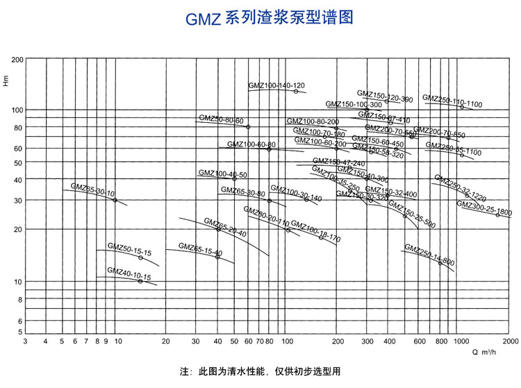
NOTE: this diagram shows the rinsing performance for the reference of initial type selection
Ⅲ、Performance and Main Technical Datas of GMZ Slurry pumps and Other pumps
Performance and Main Technical Datas of GMZ Slurry pumps and Other pumps(1)
|
Model |
Pump lift
(m) |
Flow rate
(m3/h) |
Rev
(r/min) |
Net positive suction head(m) |
Efficiency
(%) |
Matching motor |
|
Model |
Power(KW) |
|
GMZ40-10-15 |
8
15
18 |
10.6
10
9.7 |
1430 |
3.5 |
38
48
50 |
Y100L2-4 |
3 |
|
GMZ50-15-15 |
8
15
18 |
16
15
13 |
1430 |
3.5 |
40
50
49 |
Y100L2-4 |
3 |
|
GMZ50-60-80 |
45
80
95 |
65
60
53 |
2950 |
4.2 |
40
50
50 |
Y200L1-2 |
30 |
|
GMZ50-80-60 |
30
60
72 |
85
80
70 |
2950 |
3.5 |
38
50
49 |
Y200L2-2 |
37 |
|
GMZ65-15-40 |
20
40
80 |
16
15
13.2 |
970 |
4.5 |
35
50
47 |
Y160L-6 |
11 |
|
GMZ65-20-40 |
25
40
80 |
24
22
21 |
1460 |
4.5 |
43
59
61 |
Y160L-4 |
15 |
|
GMZ65-20-80 |
40
80
100 |
25.1
24.4
19.7 |
1470 |
4 |
58
72
69.6 |
Y180M-4 |
18.5 |
|
GMZ65-30-10 |
32 |
5 |
1460 3.5 |
30 |
Y132M-4 |
7.5 |
|
30 |
10 |
38 |
|
29 |
12 |
42 |
|
GMZ65-30-70 |
35
70
85 |
37.7
34
32 |
1470 |
4 |
34
52
54 |
Y180M-4 |
18.5 |
|
GMZ80-30-80 |
40
80
100 |
35
34
30 |
1470 |
4 |
44
55
57 |
Y180M-4 |
18.5 |
|
GMZ80-20-110 |
60
110
130 |
26
22
20.6 |
1470 |
4.5 |
64.8
70
72 |
Y180M-4 |
18.5 |
|
GMZ100-50-120 |
55 |
60 |
1480 |
4.5 |
64.8 |
Y225S-4 |
37 |
|
51 |
120 |
70 |
|
49 |
140 |
72 |
|
GMZ100-18-170 |
90
170
200 |
21
16
14.5 |
970 |
4.5 |
54
56
60 |
Y200L2-6 |
22 |
|
GMZ100-24-120 |
60
120
140 |
26.8
24
23 |
980 |
4 |
43
62
66 |
Y225M-6 |
30 |
|
GMZ100-25-200 |
100
200
220 |
30
25
22 |
1470 |
4.8 |
66.5
84.6
78.5 |
Y200L-4 |
30 |
|
GMZ100-27-140 |
70
140
170 |
31
27
24 |
1470 |
4.5 |
53
63
62 |
Y200L-4 |
30 |
|
GMZ100-30-80 |
40
80
100 |
34.2
32.2
20.2 |
970 |
3.5 |
35
55
39.5 |
Y200L2-6 |
22 |
|
GMZ100-30-140 |
80
140
160 |
35.5
33.7
33 |
1470 |
3.8 |
41
54.4
56 |
Y200L-4 |
30 |
|
GMZ100-30-200 |
100
200
240 |
34
30
28 |
1480 |
4.8 |
53
64
63 |
Y225S-4 |
37 |
|
GMZ100-35-250 |
130
250
300 |
38
35
28 |
1480 |
5 |
54
68
71 |
Y250M-4 |
55 |
|
GMZ100-40-50 |
30
50
60 |
40
39
37 |
1470 |
4.5 |
30
31
36 |
Y180L-4 |
22 |
|
GMZ100-40-200 |
120
170
200 |
53.7
51
44 |
1480 |
4.6 |
56
66
70 |
Y250M-4 |
55 |
|
GMZ100-52-80 |
40
80
100 |
56
55
53 |
1480 |
4 |
43.3
56
58 |
Y225M-4 |
45 |
|
GMZ100-60-80 |
40
80
120 |
64
60
62.4 |
1480 |
4 |
21
39
49 |
Y225M-4 |
45 |
|
GMZ100-80-80 |
82 |
40 |
1480 |
4.6 |
28 |
Y250M-4 |
55 |
|
80 |
80 |
39 |
|
75 |
120 |
50 |
|
GMZ100-60-200 |
90
195
240 |
71.3
69.3
67.3 |
1480 |
4.5 |
33
52.4
59 |
Y280M-4 |
90 |
|
GMZ100-70-180 |
120
180
210 |
78
77
76 |
1480 |
4.5 |
47
58
63.3 |
Y315S-4 |
110 |
|
GMZ100-80-200 |
100
200
240 |
82
80
76 |
1480 |
4.5 |
31
55
56 |
Y315S-4 |
110 |
|
GMZ100-95-250 |
120
250
300 |
104.8
102.9
99.3 |
1485 |
5 |
36
63
69 |
Y315L1-4 |
160 |
|
GMZ100-105-100 |
94 |
103.8 |
1480 |
4.5 |
26 |
Y315S-4 |
110 |
|
105 |
103.5 |
28.5 |
|
113 |
104 |
30.6 |
|
GMZ100-140-120 |
60
120
140 |
14.48
142.9
140.2 |
1488 |
4.5 |
20
34
38 |
Y355M3-4 |
250 |
|
GMZ125-70-200 |
165 |
70.8 |
1480 |
4..5 |
58.4 |
Y280M-4 |
90 |
|
212 |
70.2 |
62.2 |
|
263 |
68.8 |
70.7 |
|
GMZ150-25-500 |
300
500
600 |
28
25
20 |
980 |
5 |
53
55
67 |
Y280M-6 |
55 |
|
GMZ150-30-320 |
200
320
360 |
29.4
28.4
26.9 |
980 |
4.8 |
52
67
68 |
Y315S-6 |
75 |
|
GMZ150-32-400 |
240
400
480 |
39.3
36.8
34 |
980 |
5 |
63
75
73 |
Y315S-6 |
75 |
|
GMZ150-40-300 |
180
300
360 |
43
40
36 |
980 |
4.3 |
52
66
66 |
Y315M-6 |
90 |
|
GMZ150-40-900 |
540
900
1080 |
43
40
37 |
990 |
5 |
62
70
65 |
Y355L1-6 |
220 |
|
GMZ150-45-500 |
300
500
540 |
56.7
53
39 |
990 |
5 |
52
63
55 |
Y355M1-6 |
160 |
|
GMZ150-47-240 |
120
240
300 |
49.3
48.9
47.7 |
980 |
4 |
33.3
53.3
58 |
Y315M-6 |
90 |
|
GMZ150-50-300 |
263 |
61 |
1480 |
4.8 |
71 |
Y280M-4 |
90 |
|
312 |
58 |
73 |
|
343 |
53 |
69 |
|
GMZ150-58-320 |
210
330
390 |
61.1
59.2
57.7 |
980 |
4.8 |
47
59
62.2 |
Y315L2-6 |
132 |
|
GMZ150-60-450 |
225
450
540 |
64
61.5
58.7 |
990 |
5 |
62
75.8
76.6 |
Y355M2-6 |
160 |
|
GMZ150-73-500 |
300
500
600 |
81
73
66 |
990 |
5 |
51
56
60 |
Y355M2-6 |
185 |
|
GMZ150-75-350 |
240
350
420 |
76
75
73 |
990 |
4.8 |
38
48
52 |
Y355M2-6 |
185 |
|
GMZ150-85-530 |
340
542
640 |
83
80
77 |
988 |
5 |
44
54
56 |
Y4004-6 |
280 |
|
GMZ150-87-410 |
246
410
492 |
90
87
86 |
990 |
4.8 |
45
62
62 |
Y355m4-6 |
200 |
|
GMZ150-90-400 |
240
400
480 |
94
90
86 |
1488 |
5.2 |
56
65
64 |
Y255M3-4 |
250 |
|
GMZ150-100-300 |
180
300
360 |
105
104
102 |
990 |
4.5 |
36
50
54 |
Y355L3-6 |
250 |
|
GMZ150-120-390 |
330
390
450 |
119
118.2
100.4 |
1488 |
5 |
49
53.3
50 |
355L2-4 |
280 |
|
GMZ200-70-550 |
300
550
600 |
74
72
70 |
990 |
5 |
45
62
63 |
Y355L1-6 |
220 |
|
GMZ200-70-850 |
500
850
1020 |
74
72
63 |
990 |
5 |
51
60
60 |
Y4005-6 |
315 |
|
GMZ250-14-800 |
480
800
960 |
16
14
12 |
740 |
5 |
63
73
74 |
Y315S-8 |
55 |
|
GMZ250-32-1220 |
730
1220
1460 |
37
32
27 |
990 |
5.5 |
63
73
73.5 |
Y355L1-6 |
220 |
|
GMZ250-55-1100 |
640
1120
1360 |
59.7
56.2
51.3 |
740 |
5.5 |
59
71
69 |
Y4506-8 |
315 |
|
GMZ250-110-1100 |
660
1100
1320 |
116
110
100 |
990 |
5.5 |
55
65
63 |
Y4506-6 |
630 |
|
GMZ300-22-2100 |
1260
2100
2520 |
25
22
21 |
740 |
6 |
54
65
66 |
Y4506-8 |
315 |
|
GMZ300-25-1800 |
1080
1800
2160 |
27
25
23 |
740 |
5.8 |
51
60
60 |
Y4007-8 |
250 |
|
GMZ300-56-2000 |
61 |
1200 |
980 |
6.5 |
63 |
Y450-7-6 |
500 |
|
|
56 |
2000 |
80 |
|
|
51 |
2400 |
78 |
Ⅳ、Points for attention for assembly
1、Bearing assembly assembling: before assembly, preheat the bearing cone within 120℃, the deep groove ball bearing must be close to fillet whose two sides are uniserial conical roller bearing. When assembly the uniserial conical roller bearing, adjust the washer at rolling bearing end cap for guarantee of axial clearance, after adjusting, rotate the shaft manually for making the rotate flexibly.
2、Shaft gland assembling: the stuffing shaft gland assembly consists of stuffing-box、shaft liner、packing ring、packing and packing gland and so on. Selection of packing: if the working pressure of pump is under 1MPa, adopt asbestos fibre soaking mica as packing, while the pressure is higher than 1 MPa or convey the corrosive slurry, adopt asbestos fibre soaking polyfluoroethylene as packing. For the mechanical sealing pump, the pump has been debugged before leave factory, there is no need for adjusting by users.
3、Pump head assembling: fasten the back pimp shell onto bracket and install the stuffing-box into back pump shell, then use back fender positioning nuts to install back fender, put the O-ring onto shaft with bond, and install auxiliary impeller as well as spiral case, next, use the bolts and fixed pressing plate to fasten the spiral case onto back pump shell, at last, install the front fender and pump shell, then make the front pump shell and back pump shell be fixed together and screw down the bolts. Additionally, when assemble, put the sealing O-ring of stuffing-box and fender、back and front fender and spiral case in correct position and impact it.
Ⅴ、Operation
1. Startup: before start, check each unit as the following procedure:
(1) The pump shall be installed onto reliable foundation without vibration, then screw down all the anchor bolts.
(2) The pipeline and valve shall be equipped with holding frame. When screw down the connecting bolts, the metal liner of some pumps may be higher than flange, so the bolts shall be screwed down properly in case cause damage to sealing washer.
(3) Rotate the rotational shaft manually to check is there is any abnormal noise, if any, adjust the clearance of impeller.
(4) Check the rotation direction of motor to see if it is the same to the direction of arrow.
(5) When direct connection driving, the pump shaft and motor shaft must be centered accurately, and the pump shaft shall be parallel with motor shaft when use belt for driving, and adjust the position of grooved pulley for making it vertical to trough belt in case cause cute vibration and friction.
(6) There is one stub tube which can be removed fixed onto the suction pipe of pump, it is convenient to carry out maintenance due to its special structure.
(7) Shaft gland inspection: check the water quantity and water pressure in shaft gland to see if they are reasonable; adjust the forcing screw of packing gland for changing the degree of tightness; then adjust the shaft gland, the leakage from packing gland should be seen as blob and blob effusion. The packing should be kept not too tight, otherwise, the shaft liner shall be hot and at the same time, energy consumption shall be increased. While the packing is too loosening, there may be too much leakage, generally, the water pressure of shaft glad shall be higher than pump outlet by 35 KPa. It is suggested that the water quantity of shaft gland shall be controlled at the range of 0.15L/S -2.1L/S according to different model. Additionally, for the pump equipped with mechanical sealing, put through the shaft glad water before open the pump.
2、Running
(1) In the process of running, check the pressure and flow rate of water in shaft gland frequently and adjust the packing gland or change the packing for ensuring there is less clean water going through the shaft.
(2) Check the running condition of bearing assembly, before start the pump, add #20 or 30 lubrication oil into bearing body, and connect the rubber hose connecter with cold water (No need for cold water for 18.5KW below). The oil quantity of bearing shall be proper and clean and should be added termly.
(3) The performance of pump shall be degraded with the increase of the clearance between the impeller and fender, so adjust the impeller forward in time for keeping the pump running in high efficiency. If the friction is serious, the spare parts shall be changes. Check the spare partstermly and estimate the useful life of spare parts in case cause serious consequence due to the failure of spare parts.
3、Termination of pumping
Before termination of pumping, make the pump draw out a certain clean water for removing the slurry, then close the pump、valve、shaft gland water and cold water in bearing body in turn.
Ⅵ、Care and maintenance
In order to make the pump run safe with long useful life, must carry out daily maintenance. When carry out maintenance, the following aspects shall be paid attention:
1、Maintenance for shaft gland:
Check the water pressure and quantity of shaft gland, keep a certain clan water to flow through the shaft all the time, check the packing gland termly as well as packing. If the packing is not enough, change it. Besides, the water pressure and quantity of shaft gland shall be in accordance with the above requirements. For the pump equipped with mechanical sealing, the mechanical sealing parts shall be added with N45 engine oil in case rusty of this part and aging of inner rubber.
2、Adjusting for impeller:
In order to keep high efficiency running, adjust the clearance between the impeller and front fender in time. Before adjust the clearance, must stop the pump, then loosen the bolts for compressing the bearing assembly, and screw the nut of adjusting bolt to make the bearing assembly forward, at the same time, rotate the pump shaft manually as the rotation direction of pump till there is friction between the impeller and front fender. Then loosen the nuts which were screwed down just by half circle, then screw down the nuts in front of the adjusting bolts for making the bearing assembly move backwards, here, the clearance between the impeller and front fender shall be kept at the range 0.5-1mm. after adjustment, recheck the impeller rotation to see if it is in normal condition and is the holding down bolts have been screwed down before restarted.
3、Lubrication of bearing
When assemble the bearing assembling, the useful life shall be longer if the assembly is correct and added with proper lubrication oil as well as proper maintenance, in the processing of running, the pump shall be added changed with lubrication oil, the time interval and injection quantity shall be related with the rev、bearing spec、continuous duty, on and off times and so on, and so the operator should accumulate the operation experience, add to oil reasonably and in time.
4、The stand by pump shall be rotated by 1/4 circle so that the bearing can bear the static load and external vibration evenly.
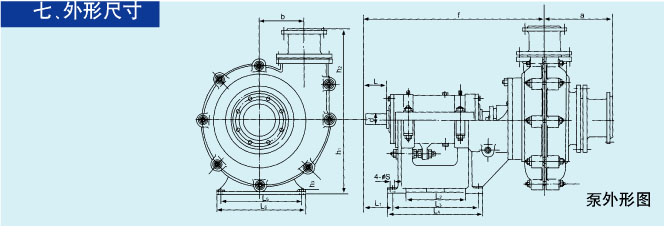
Ⅶ、Overall dimension
Outline drawing for pump
|
Model |
pump |
Pump bottom |
Shaft tip |
|
a |
b |
f |
h1 |
h2 |
L1 |
L2 |
L3 |
L4 |
L5 |
L6 |
H3 |
S |
d |
L |
|
GMZ40-10-15 |
260 |
120 |
640 |
250+0.5 |
300 |
127 |
208 |
308 |
348 |
300 |
340 |
25 |
18 |
Φ40 |
110 |
|
GMZ50-15-15 |
264 |
140 |
641 |
250+0.5 |
333 |
127 |
208 |
308 |
348 |
300 |
340 |
25 |
18 |
Φ40 |
110 |
|
GMZ50-60-80 |
255 |
120 |
639 |
250+0.5 |
333 |
127 |
208 |
308 |
348 |
300 |
340 |
25 |
18 |
Φ40 |
110 |
|
GMZ50-80-60 |
264 |
140 |
641 |
250+0.5 |
333 |
127 |
208 |
308 |
348 |
300 |
340 |
25 |
18 |
Φ40 |
110 |
|
GMZ65-15-40 |
|
| 更新时间:2011/11/14 |
|